25.04.2020
Any technology program is best tested on real equipment. This allows you to find inaccuracies in the code and algorithms that are embedded in its work. At the training stage, during the training process, when the PLC programming experience is still not enough, laboratory mock-ups play a crucial role – they develop the skill of engineers to anticipate the possible consequences of an error in the program. For this, mock-ups of real devices, machines or even entire automated production sites are created.
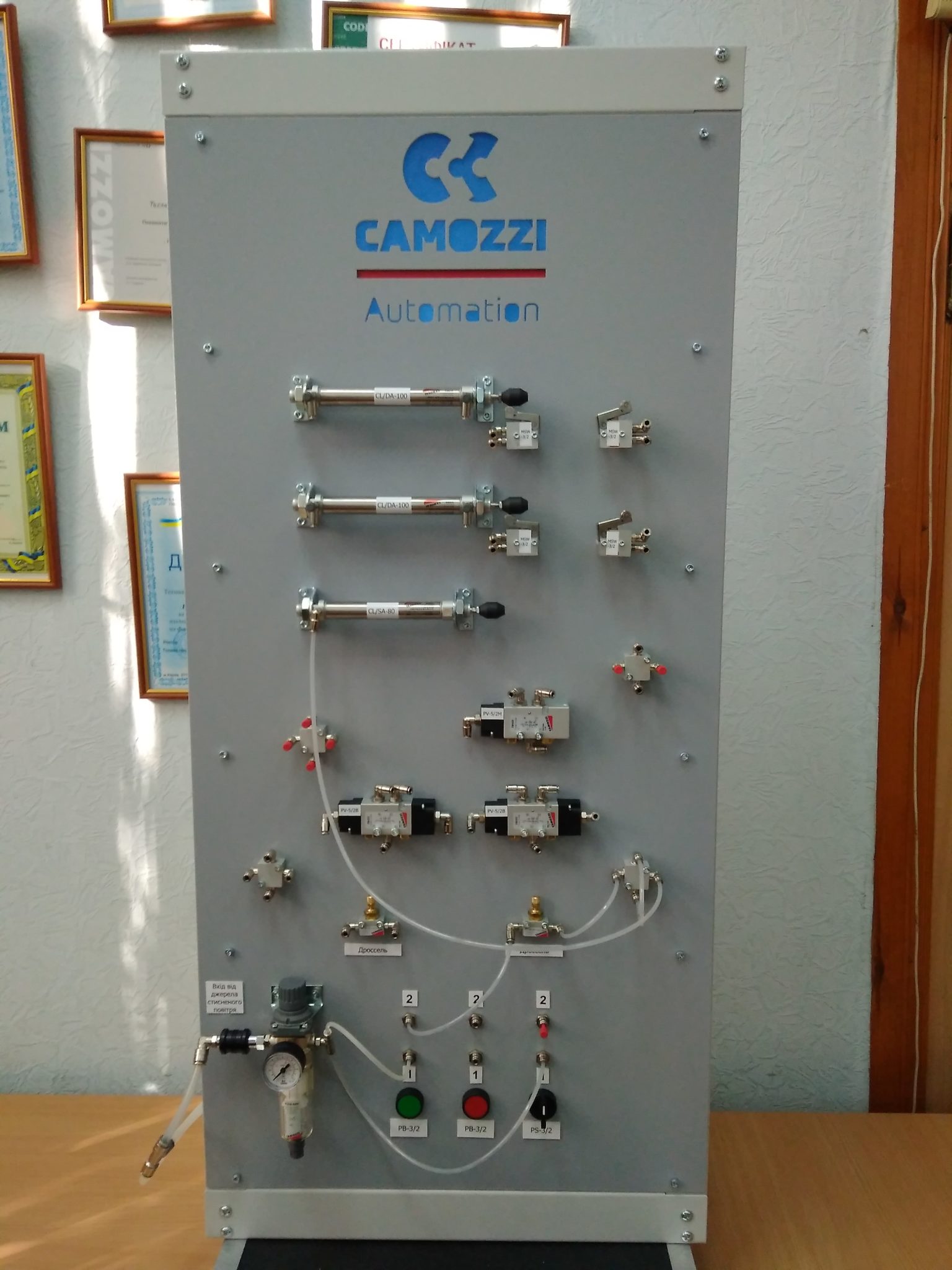
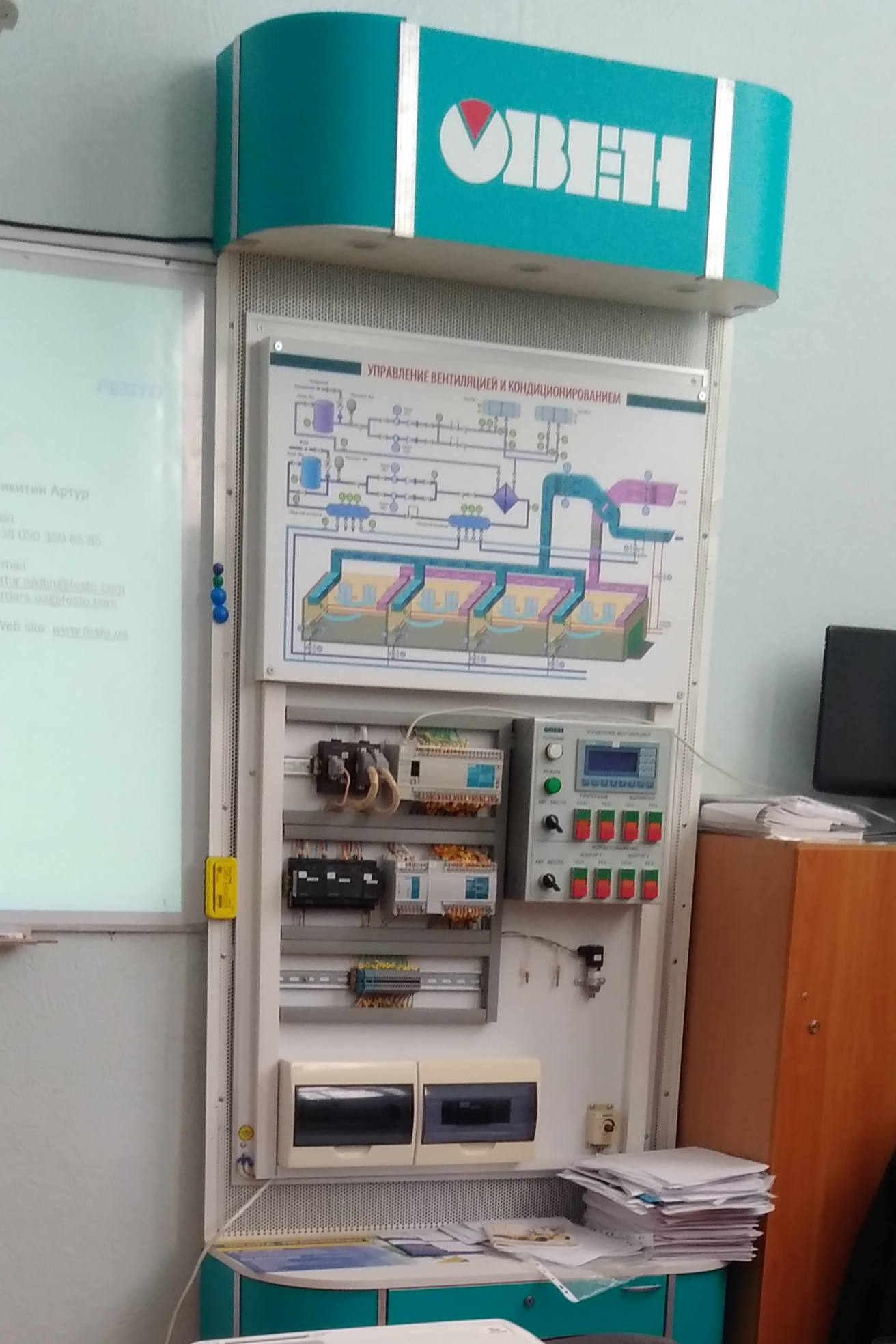
Stands of OWEN and CAMOZZI Automation
At the CITAM Department in the laboratory of Industrial Automation and Mechatronics. S.V. Denisova ”, several specialized training stands have been introduced into the educational process in which industrial programmable logic controllers and automation tools are combined with educational mock-ups. This is the stand of OVEN company “Automation of ventilation control at a manufacturing enterprise”, Educational and methodical laboratory complexes from the company “CAMOZZI Automation” – “Pneumatics”, “Pneumatic drives and mechatronics”.
Laboratory model of a stamping machine
Also, in the laboratory, teachers and students create sets of educational equipment and actuators for laboratory work with their own hands. With the help of such kits, a working model of an automated electronics electronics fundraising site is gradually created to simulate the basic principles of modern production in the framework of Industry 4.0.
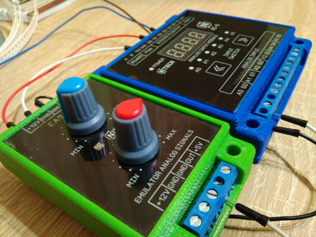
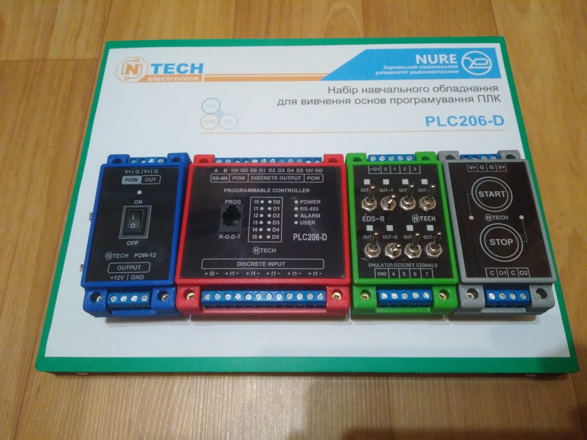
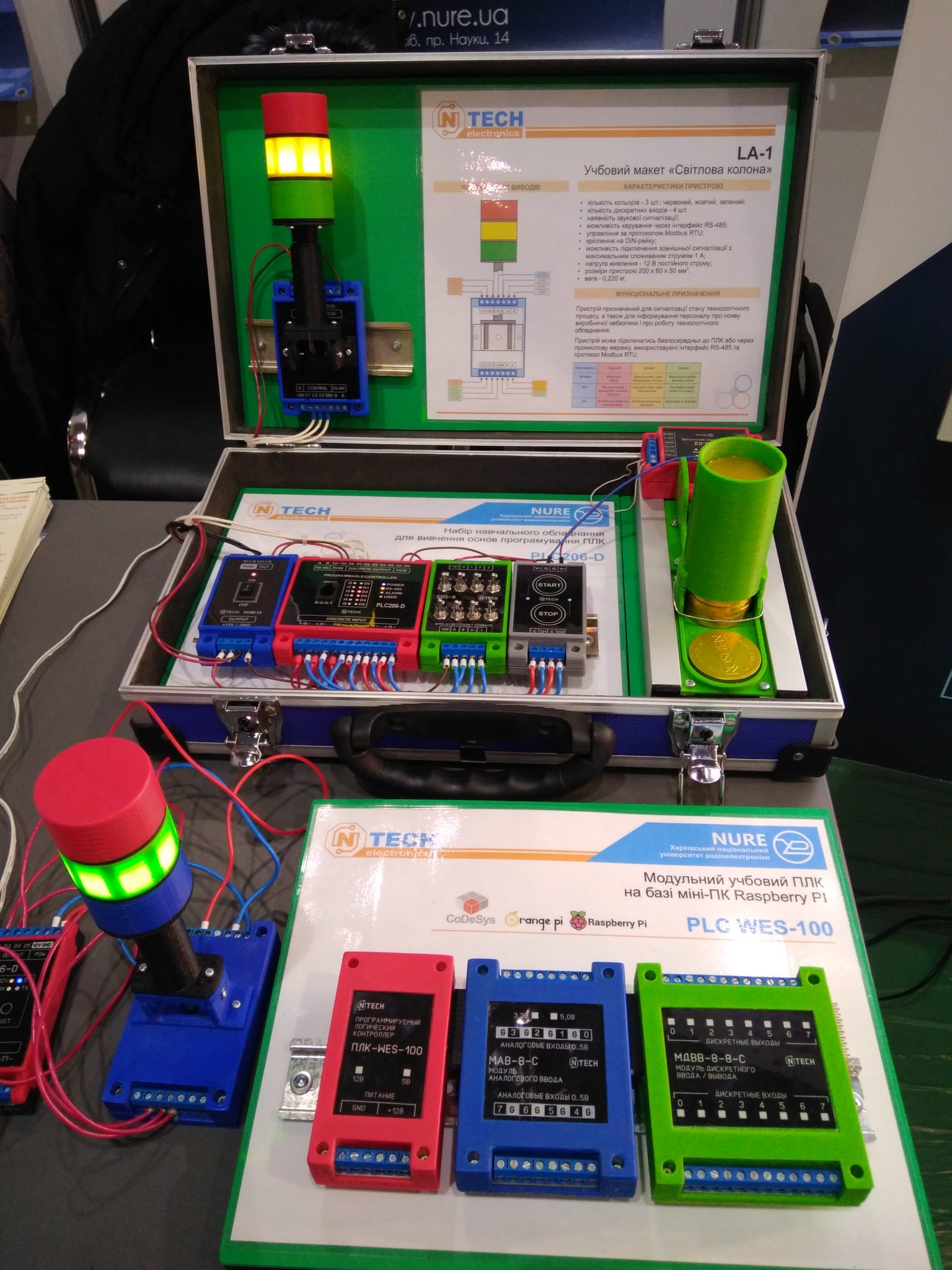
The following models have already been made and introduced into the educational process: educational controller, programmable; discrete input-output module; analog input module; stamping machine layout; light column layout; a modular PLC based on the Raspberry PI mini-PC.
The advantage of laboratory layouts is the ability to visually see the results of the PLC program in action using real equipment as an example. Lab mockups created for the educational process.
Create a visual interface in the Codesys IDE
Features of the use of models – this is their limited number and the ability to work with them only when conducting laboratory work, or after training in scientific student groups. But, as practice shows, some students want to continue research at home, performing individual tasks, or studying unscheduled materials. In such cases, a logical question arises – how to provide everyone with a personal laboratory stand. The answer is on the surface: use virtual analogues of real layouts.
The concept of virtual layouts provides the ability to most fully simulate the behavior of real devices. This also applies to the animation of moving the moving parts of the device and how to connect to the layout itself.
Some integrated developer environments have built-in visualization tools with which the engineer can create graphical control interfaces and display information received from sensors. For example, in the Codesys IDE, such a Visualization component that allows you to create various visualization screens using graphical primitives.
There are also tools that only allow you to write program code in one of the technological programming languages, or in a language traditional for programmers and have no way to visually display the status of the equipment.
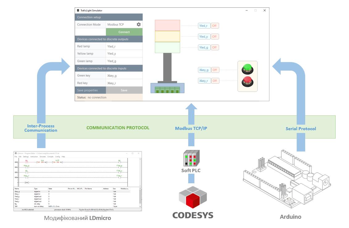
Distance learning has made adjustments to the schedule of the educational process and has shown the importance of each component in the training of modern specialists in “hardware” specialties. Already in the first weeks, the lack of the ability to use specialized mock-ups by students at home when performing laboratory work was acutely felt. Therefore, it was decided to create a universal software platform for virtualizing existing laboratory layouts and developing new ones. The platform was based on the possibility of interacting with a virtual device through several communication protocols: Serial Protocol, Modbus TCP / IP, Inter-Process Communication. The latter was chosen because it is almost impossible to integrate a virtual layout into an existing one.
The competencies of professional training of future specialists, as well as current trends in the development of electronic equipment using Arduino among students and even schoolchildren were also taken into account.
For example, Serial Protocol is widely used during a combination of peripherals with Arduino controllers, as well as no less popular in industrial automation. The implementation of this protocol in a virtual layout makes it possible to use it not only to connect to the software development environment and debug the written program, but also to use the program independently as an independent virtual device.
Modbus TCP / IP is used in industry to connect automation equipment to a single industrial network. When creating software for checking the correct functioning with a certain version of the PLC without the presence of the device itself, the possibility of software simulation is built into various IDEs. But, for example, in the Codesys integrated environment there is a significant drawback – this is not the ability to test the interaction algorithm between several devices using communication protocols, as well as the lack of direct access from the program whose operation is simulated to the control object. Using the Modbus TCP / IP protocol in combination with Codesys Control Win V3 makes it possible to combine the Codesys environment and the virtual layout directly in simulation mode.
In the process of learning the basics of PLC programming, the LDmicro software tool is used. This project is developing dynamically, has open source code, and turns an ordinary microcontroller into an “industrial” controller programmed using the technological language LD. Now this project has already spread to such families as AVR, PIC, STM, ESP, Arduino. Thus, students can use their modules on the basis of these microcontrollers for self-assembly of automation tools for their own projects. The presence of open code made it possible to make the necessary changes in the program and add a feature such as the exchange of data between completely independent programs through named pipes (Named Pipes) using IPC technology (Inter-Process Communication).
By combining all these technologies, it was possible to create a universal platform for the further development of virtualization of laboratory training layouts. It consists of three levels: communication, data processing, visualization.
The general communication layer is used to interact with third-party software environments for the development of technological programs, or even with hardware.
The level of accumulation and processing of data is used to exchange information between the lower and upper levels. At this level, the interpretation of the variables used in the technological program and the data arrays with which the graphic components work is performed.
Visualization of the process takes place at the top level. It is created by C # programming tools and its appearance depends on the principle of operation of that layout, the action of which is simulated and can be implemented as 3D or 2D animation. Using the built-in property editor, variables are assigned and assigned to the corresponding graphic components. Further, the received data is visualized, and dynamic components, for example, buttons, generate a stream of information that affects the progress of the technological program. Thus, the emulation of the operation of a real device.
Such a structure made it possible to develop various virtual layouts with the necessary graphic content, but based on the general principle of interaction with technological program development tools, it was laid down at the lower levels. Gradually supplementing the communication layer with support for new protocols, the scope of application of existing virtual layouts will expand.
(с) prof. of CITAM department S. Novoselov